|
This file is available on a Cryptome DVD offered by Cryptome. Donate $25 for a DVD of the Cryptome 10-year archives of 35,000 files from June 1996 to June 2006 (~3.5 GB). Click Paypal or mail check/MO made out to John Young, 251 West 89th Street, New York, NY 10024. Archives include all files of cryptome.org, cryptome2.org, jya.com, cartome.org, eyeball-series.org and iraq-kill-maim.org. Cryptome offers with the Cryptome DVD an INSCOM DVD of about 18,000 pages of counter-intelligence dossiers declassified by the US Army Information and Security Command, dating from 1945 to 1985. No additional contribution required -- $25 for both. The DVDs will be sent anywhere worldwide without extra cost. | |||
Space Handbook
_____________________________________________________
Spacelift, assigned to Air Force Space Command (AFSPACECOM) in October 1990, is the command's newest operational mission. To get a clearer idea of what spacelift is, we must first look at a definition of the mission. Air Force Manual 1-1, Basic Aerospace Doctrine of the United States Air Force, states that "spacelift projects power by transporting people and materiel to and through space.''1 Therefore, spacelift's objective is to launch and deploy new and replenishment space forces at any level of conflict.2 Spacelift is accomplished by a joint ensemble of military, civil service, and civilian contractor personnel. They process, integrate, assemble, analyze, and launch today's space launch vehicles. These vehicles and the launch bases used today were, for the most part, developed in the 1950s and 1960s. But, as Vice President Dan Quayle stated in his fall 1991 announcement of the new National Launch Strategy:
The current systems are not obsolete. Systems like the Atlas, Delta, Titan, and the Space Shuttle will continue to provide the nation's primary launch capabilities at least through the end of the decade and into the 21st century.3
This chapter presents the major areas of spacelift. The discussion includes an overview of major launch vehicles and a short look at the launch process.
US launch bases consist of two major facilities operated by Air Force Space Command. Cape Canaveral Air Force Station (AFS), Florida, and Vandenberg Air Force Base (VAFB), California. The Department of Defense established the 45th Space Wing at Cape Canaveral Air Force Station and the 30th Space Wing at Vandenberg Air Force Base, also known as the Eastern and Western Ranges respectively. These national assets provide the space, facilities, equipment, and systems required to develop and test aeronautical, space launch, missile, and other technical and scientific programs and activities. Both ranges share similar responsibilities. With their vast arrays of radar, telemetry receivers, optical trackers, and command transmitters, the ranges track missile flight and destroy those that deviate off course. The consequences of failing in this task are so potentially disastrous that this job takes on great significance. In addition to performing important missile safety functions, the ranges provide valuable telemetry relay and analysis for space, ballistic, and aeronautical operations. Telemetry information allows quick failure analysis and aids in the development of future aerospace systems.
The Eastern Range consists of a series of stations, including Cape Canaveral Air Force Station, and the Jonathan Dickinson Tracking Annexes on the Florida mainland. Also part of the Eastern Range are Antigua Air Station (AS) in the West Indies and the British-owned Ascension Auxiliary Air Field in the south Atlantic Ocean. Range instrumentation ships, such as the USNS Redstone and a fleet of advanced range instrumentation aircraft from the 4950th Wing at Wright-Patterson Air Force Base, Ohio, can augment these stations. In addition, the Eastern Range may use other DOD and/or National Aeronautics and Space Administration (NASA) facilities to meet the requirements of any mission or operation.
The Western Range provides multifaceted research and development test capability and management of a network of test facilities throughout California, Hawaii, and the south Pacific Ocean area. The range uses radar, optic, telemetry, and communication instrumentation to acquire critical data that serves as the basis for improvements in US ballistic, space, and aeronautical systems.
In the process of facilitating access to space and space operations as directed by the chief of staff of the Air Force, AFSPACECOM assumed command and control of the Air Force launch bases, ranges, and associated facilities. As current and planned launch systems complete development, they will transition to AFSPACECOM operational elements, which will assume responsibility for providing all required launch services.
Vandenberg AFB can trace its heritage to the beginning of World War II when it was a major US Army training base. Construction of the 90,000-acre Army installation started in September 1941. The Army designated the installation Camp Cooke in honor of Maj Gen Philip St. George Cooke, a cavalry officer during the Mexican-American war. From its activation on 5 October 1941 to the end of World War II, armored and infantry divisions trained at the camp. In 1944 the Army established a prisoner of war camp there, which eventually accommodated over 8,700 German and Italian prisoners. Additionally, a maximum security Army Disciplinary Barracks (now the US Penitentiary, Lompoc) was constructed on the camp. The Army deactivated Camp Cooke in June 1946, only to reactivate it from 1950 through 1953, after the outbreak of the Korean conflict.
While engaged in intercontinental ballistic missile (ICBM) studies coupled with advancements in rocket design and thermonuclear research, the Air Force transformed Camp Cooke to an ICBM training base and on 7 June 1957 renamed it Cooke Air Force Base. The Air Force revamped the old Army training camp to a modern missile launch and control complex and renamed it Vandenberg AFB in October 1958 to honor Gen Hoyt S. Vandenberg, second Air Force chief of staff and an aerospace advocate. Two months later, the launch of a Thor intermediate range ballistic missile marked the first major operation from the Western Test Range.
Over the years, launch, ballistic, and aeronautical activity at Vandenberg has steadily increased, and VAFB continues to be the primary launch location for polar-orbiting satellites and operational ICBMs. The base is ideally suited for polar and retrograde launches with inclinations from 70 to 104 degrees. Currently, there are five active space launch complexes at Vandenberg AFB (table 2). Space Launch Complex 6, built for the space shuttle, is in mothball status.
Table 2
Launch Capability in California
Location |
Type of Missile |
| Space Launch Complex 2W | Delta |
| Space Launch Complex 3W | Atlas E |
| Space Launch Complex 4W | Titan II |
| Space Launch Complex 4E | Titan IV |
| Space Launch Complex 5 | SCOUT |
Source: Maj Dale Madison, USAF, interview with the editor, December 1991.
As with Vandenberg AFB and the Western Range, the origins and development of Cape Canaveral and the Eastern Range date back to the beginning of World War II. Work began in December 1942 on the Banana River Naval Air Station in response to public and military recognition of the vulnerability of the Florida east coast to enemy attack. The Navy originally established the station as an auxiliary operating base of the Atlantic Coast Defense System, but it rapidly grew with the arrival of World War II and the need for antisubmarine capability. The Navy inactivated the station and placed it in caretaker status on 1 August 1947.4
Meanwhile, Joint Chiefs of Staff (JCS) committee on guided missiles recommended that a committee be formed to find a location for a long-range missile proving ground. In October 1946, the JCS created the committee on Long-Range Proving Ground to study possible locations, and in June 1947, the committee selected two candidate sites. The first choice was located at El Centro, California, and extended to Baja California. Initial negotiations with the Mexican government proved fruitless, and the US soon abandoned this choice. The second choice was the Banana River-Bahama Island range with the launch site located at Cape Canaveral. This area was ideal because the nearby river offered a security and safety buffer, and the site had an unlimited overwater test area in the south Atlantic Ocean. The British proved accommodating to negotiations for the establishment of instrumentation stations in the Bahamas, and the US and Great Britain signed a preliminary agreement in February 1949. They signed the final document, known as the Bahamian Agreement, 21 July 1950.5
The Navy, in anticipation of these developments, transferred the Banana River Naval Air Station to the newly independent Air Force. The nucleus of what became the Air Force Missile Test Center and eventually the Eastern Space and Missile Center was formed with the establishment of the Advance Headquarters, Joint Long-Range Proving Ground on 1 October 1949.6
On 16 May 1950, the Air Force redesignated this organization the Long-Range Proving Ground Division and assigned to it the functions and responsibilities of a major air command. This redesignation marked the end of the joint service proving ground as the Air Force took sole responsibility. The Long-Range Proving Ground lost its major air command status with assignment to the newly organized Air Research and Development Command, the predecessor of Air Force Systems Command. The division acquired the status of a numbered Air Force and in June 1951 became the Air Force Missile Test Center. In May 1954, the Air Force designated the organization the Air Force Eastern Test Range, and on 1February 1977 it became Detachment 1, Space and Missile Test Center. On 1 October 1979, the organization became the Eastern Space and Missile Center. Most recently, on 1 October 1990, Air Force Space Command took over launch operations from Space Systems Division establishing the 45th Space Wing and the 1st Space Launch Squadron (SLS). The 1st SLS assumed launch responsibility for the Delta II booster.7
The Eastern Range and its predecessors have been involved in testing and development of missiles for the nation's defense. Since the late 1950s, the Eastern Range has played a crucial role in the development of the national space program. The first launch from the site occurred on 24 July 1950 when the Eastern Range successfully launched a Bumper 8, a German V-2 with a modified second stage. Then on 31 January 1958, in response to the launch of sputnik, the Eastern Range launched the Explorer I from the cape. This launch also marked the beginning of partnership with NASA in manned and unmanned space programs.8
Cape Canaveral Air Force Station (CCAFS) is adjacent to NASA's Kennedy Space Center. Range safety limitations restrict launches from the cape to orbital inclinations from 28.5 to 57 degrees to prevent overflights of Newfoundland and the Bahamas.9 Currently, there are eight active space launch pads at CCAFS and the Kennedy Space Center (table 3).
Table 3
Launch Capability in Florida
Location |
Type of Missile |
| Space Launch Complex 17A/B | Delta II |
| Space Launch Complex 36A | Atlas II |
| Space Launch Complex 36B | Atlas I |
| Space Launch Complex 40 | Titan IV/IUS |
| Space Launch Complex 41 |
Titan IV/IUS and Titan IV/Centaur |
| Space Launch Complex 39A/B | Space Shuttle |
Source: Maj Dale Madison, USAF, interview with the editor, December 1991.
There are three categories of today's launch vehicles. The first category contains the small launch vehicles, the solid controlled orbital utility test (SCOUT) and the Pegasus which are capable of carrying from 500 to 1,000 pounds into low-earth orbit.
The medium class of the Delta II, the Titan II, and the Atlas I and II is next. The Delta II can boost approximately 4,010 pounds to geostationary transfer orbit (GTO). The Titan II can boost about 4,200 pounds to a 100-nautical-mile polar orbit, and the Atlas II can carry about 5,800 pounds to GTO.
Lastly, the heavy lift vehicles include the Titan IV and the Space Transportation System (STS). The Titan IV inertial upper stage (IUS) can carry 5,350 pounds to geosynchronous earth orbit (GEO) and with a Centaur upper stage it can deliver approximately 10,000 pounds to GEO. The Titan IV can carry 32,000 pounds into a low-Earth polar orbit. The space shuttle carries approximately 53,000 pounds into low-Earth orbit.10
Vought Astronautics (now Ling-Temco-Vought) developed the SCOUT from a requirement of the National Advisory Committee on Aeronautics (NACA) (the forerunner of NASA) for a small space launch vehicle. Paralleling this effort was the Air Force's interest in advanced solid rocket motors. Thus, the Air Force and NACA agreed to a joint development program--the SCOUT--to be based at Langley Field, Virginia, in 1958.
Vought Astronautics was given a contract in 1959 to design and develop structural elements of the SCOUT vehicle and launch tower. In 1960, NASA increased Vought's responsibilities as sole integrator. This role included responsibilities from design and fabrication to payload integration and launch. The SCOUT has had a flight success rate of 95.5 percent since its first launch in December 1963.
The SCOUT was the first US launch vehicle to use solid fuel exclusively in all stages. The standard SCOUT is a four-stage vehicle approximately 75 feet in length, with an optional fifth stage available for launching smaller payloads into higher elliptical orbits.
The SCOUT employs a dual-purpose launcher/transporter combination that permits checkout of the vehicle in the horizontal position and launching in the vertical position. The launcher has a movable base which permits azimuth control up to 140 degrees. A cantilevered elevating launch boom provides pitch control to the 90-degree vertical position.
Vought based the original first-stage Algol I rocket on an early version of the Polaris missile. This rocket provided 86,000 pounds of thrust and had a length of 31 feet. Next came the Algol IIA, Algol IIB, and the current Algol IIIA, which produces 104,500 pounds of thrust. A system featuring a combination of jet vanes and control surfaces guides the first stage during the thrust phase and during the coast phase after engine burnout.12
As the first stage evolved from the Polaris missile, Vought derived the second stage from the Sergeant missile. The Sergeant stage, more commonly known as the Castor, has been a part of many different sounding rockets and space launch vehicles. The SCOUT has used the Castor I and Castor II motors. It currently uses the Castor IIA motor, which measures 20.7 feet and provides 60,000 pounds of thrust.13
The third stage of the SCOUT is the Antares IIIA motor, which is 11.2 feet long and provides 18,200 pounds of thrust. It uses a thrust system similar to stages one and two, but has hydrogen peroxide reaction jet motors for control. The fourth stage includes the payload and an Altair IIIA motor producing 5,800 pounds of thrust.14
There are two active launch sites for the SCOUT--NASA's Wallops Flight Facility on Wallops Island, Virginia, used for eastern launches, and Space Launch Complex 5 at Vandenberg AFB, California, used for high inclination missions. The Wallops Flight Facility, developed after World War II to launch sounding rockets, is located on an island in northeast Virginia. In the past three decades, the Wallops complex has launched more than 14,000 rockets and missiles. Its first orbital launch took place in 1960 using the SCOUT. Since then 20 SCOUTs have orbited from this site.15 There are two SCOUT boosters remaining. One is reserved for a space test program payload and the other for a SDIO experiment. Both are expected to be launched in 1993.
[Image 6K]
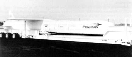
Pegasus
The second of the small launch vehicles is the Pegasus, which is a three-stage, solid-propellant, all-composite, winged rocket. The Pegasus provides a cost-effective, reliable, and flexible means of placing small payloads into suborbital or orbital trajectories. This air-launched space booster is the product of the privately funded, joint venture of Orbital Sciences Corporation and the Hercules Aerospace Company.
The Defense Advanced Research Projects Agency conducted the first two Pegasus launches as part of its Advanced Space Technology Program to test and evaluate the vehicle for future military operations. The maiden flight of the Pegasus air-launched space booster on 5 April 1990 marked the first time an air-launched rocket placed a payload in orbit. This first flight began over the Pacific Ocean at an altitude of 43,200 feet. NASA's NB-52 aircraft, the same aircraft that launched the X-15, released the Pegasus.16 First stage ignition occurred after it had fallen five seconds to clear the host aircraft. Pegasus then lifted itself to a trajectory that successfully carried its 423-pound payload to a 273 x 370 nautical mile, 94-degree inclination orbit.17
Pegasus is comprised of seven major elements: three solid rocket motors, a payload fairing, a delta-shaped lifting wing, an avionics assembly, and an aft skirt assembly that includes three movable control fins. A modified conventional transport/bomber class aircraft (B-52, L-1011, etc.) can carry Pegasus to a nominal flight level of 40,000 feet and a speed of Mach 0.8.18 After release, the vehicle free falls with active guidance to clear the carrier aircraft while executing a pitch-up maneuver to place it in the proper attitude for motor ignition. After stage one ignition, the vehicle follows a lifting-ascent trajectory to orbit. The Pegasus is 50 feet long and 50 inches in diameter with a gross weight (excluding payload) of 41,000 pounds. A delta wing with a 22-foot span and three eight-foot movable control fins are mounted on the first stage.19
Several factors contribute to the performance of the Pegasus. First, there is the potential and kinetic energy contributed by the carrier aircraft. Next is reduced drag due to lower air density at the higher altitudes at which it is launched. Also, higher nozzle expansion ratios provide for improved propulsion efficiency in addition to the reduced gravity losses due to its unique flat trajectory and wing-generated lift.
Pegasus can deliver payloads up to 900 pounds to low-Earth orbits or payloads up to 1,500 pounds on suborbital, high-Mach-number cruise, or ballistic flights. Payloads as large as 72 inches long and 46 inches in diameter can fit within the standard payload fairing.20 Through a choice of launch points and azimuths, Pegasus can achieve a complete range of circular and elliptical orbits, with a wide variety of prograde and retrograde inclinations.
Advantages over conventional pad-launched boosters include an increased range of orbital inclinations achievable without energy wasting maneuvering during the launch phase and extended launch windows resulting from the flexibility of launch point selection. Additionally, ascent profiles generate lower acceleration, dynamics pressure, and structural and thermal stress providing the payload a gentler ride into orbit.
One of the most significant advantages of the Pegasus system is the elimination of the ground launch pad and the need for lengthy launch pad refurbishment. The carrier aircraft requires only routine aircraft maintenance after each flight and standard periodic maintenance. Also, as already noted, air launch allows flexibility in selecting the launch point. This flexibility can be used to optimize the mission trajectory, improve range support coverage, provide a greater range of available launch azimuths, heighten operational security, and minimize environmental impacts via remote over-water launching. Furthermore, this flexibility provides the ability to choose a launch point anywhere in the world, which allows first pass orbit coverage over any point on the Earth's surface.
Pegasus also offers flexibility in other areas. The launch location can be chosen to, in some cases, double the standard 10-20 minute Sun-synchronous launch window. Air launching provides greater launch availability since the carrier aircraft can launch the vehicle above most weather systems. Unlike vehicles requiring fixed launch sites, the Pegasus can deliver payloads to any desired inclination, from equatorial to beyond Sun-synchronous from a single base of operations. Since the vehicle and payload are integrated in a processing facility and not on the launchpad, separate missions can be readied for launch simultaneously.
The first medium-class launch vehicle to be discussed is the Delta. The Delta space launch vehicle has been the workhorse of the US booster inventory. Since 1960, it has been launched over 200 times with an impressive success rate of 98.4 percent.21 The family of Delta launch vehicles originated in 1959 when NASA's Goddard Space Flight Center awarded a contract to Douglas Aircraft Corporation (now McDonnell Douglas Corporation) to produce and integrate 12 launch vehicles capable of carrying medium-class payloads. The baseline Delta (launched in 1960) used a modified Air Force Thor-Able intermediate range ballistic missile configuration as the first stage. Its second and third stages came from the Vanguard.
The Delta has evolved to meet the needs of its users. It serves both Cape Canaveral and Vandenberg and has shown its reliability while launching a variety of payloads. Its lift capacity to geosynchronous transfer orbit has grown from 100 pounds in 1960 to approximately 4,500 pounds with the current Delta II.22
[Image 9K]
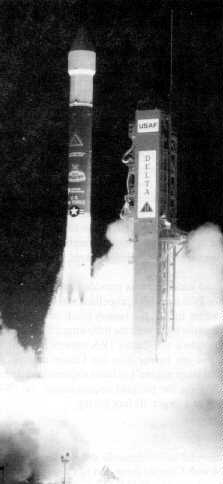
Delta II
The 1960s saw performance increase with the use of more powerful motors, enlarged fuel tanks, and strap-on solid rocket motors to supplement thrust. A major change in the rocket came in 1968 with the development of the Long Tank Thor. Modifications occurring from this development included the expansion of the diameter to eight feet and increased tankage in both stages of the vehicle. In addition, designers increased the number of the solid rocket strap-on motors from three to six, improving performance by 27 percent.23
The 1970s and 1980s saw further major improvements to the Delta vehicle. The 3990 series was the culmination of the improvements. The 3990 was the first rocket to make use of the powerful Castor IV solid motor.24 Each Castor IV produced 85,000 pounds of thrust compared to 52,200 pounds for the Castor II motors. An optional third stage called the payload assist module (PAM) accompanied this series. The PAM originally supplemented the space shuttle by transferring satellites from low-Earth parking orbit to their final operational orbits.
An unprecedented string of US launch vehicle failures occurred in 1985 through 1987, seriously impeding the US's ability to place payloads in space. The Delta II (6925 and 7925 series), which resulted from the USAF medium launch vehicle I (MLV I) competition, revitalized the nation's launch capability. This new generation of Delta vehicles primarily launch Global Positioning System (GPS) satellites and provides for the needs of domestic and international commercial communication satellite users.
A Rocketdyne RS-27 engine provides power to the Delta IIs' first stage. The RS-27 is a single start, liquid bi-propellant (RP-1 and liquid oxygen engine). The first stage also has two vernier engines to provide roll control during main engine burn and attitude control after cutoff and before second stage separation. Stretching the first stage by 12 feet over earlier versions (to accommodate a 4.7-foot and 7.3-foot lengthening of the fuel and oxidizer tanks) increased lift capability.25
The second stage has a restartable Aerojet AJ 10-11 8K engine developed for the USAF. It uses nitrogen tetroxide and Aerozine-50 for propellants. The forward section of the second stage houses guidance and control equipment that provides guidance sequencing and stabilization signals for both the first and second stages.
The Delta's third stage (used if dictated by the mission profile) is the Star-48B solid rocket motor. The Star-48B is supported at the base of the motor in a spin table that mates to the top of the second stage guidance section. Before third stage deployment, the Star-48B and payload are spun-up using rockets. This stabilizes the third stage during deployment.26
Nine Castor IVA solid rocket motors provide liftoff thrust augmentation for Delta II 6925 series. The Castor IVA uses new propellant and a new exit cone to increase thrust.
The Delta II 7925 series fulfills the launch needs of GPS and commercial satellites. Basically, it is the same as the 6925 with the following differences. Nine Hercules graphite epoxy motors (GEM) replace the Castor IVA motors. The GEMs are six feet longer, provide more thrust, and are lighter than the Castor motors. Additionally, designers increased the RS-27 first stage engine's exhaust expansion ratio from 8:1 to 12:1 to boost performance. Depending on the payload requirements, the 7925 can use the 6925's 9.5-foot payload fairing or a larger 10-foot fairing.27
[Image 18K]
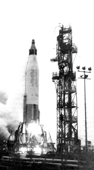
Atlas
The Atlas intercontinental ballistic missile development project began in 1945 as Air Force Project MX-774 with Convair (now part of General Dynamics) as contractor. The Air Force cancelled the program in 1 947 for lack of funds only to reinstate it in 1951. The basic one-and-a-half stage design has changed little in over 40 years and 500 ICBM and space launches. Significant advances in its capability and adaptability are reasons the Atlas has become the "DC-3" of space launch vehicles.
The Atlas is unique in the space launch vehicle world because its propellant tanks serve as the primary structure. The rocket is of thin stainless steel construction and uses internal pressure to stabilize itself, thus creating a "steel balloon." The original Atlases had skin gages ranging from 0.016 to 0.040 inches. The newest version, the Atlas IIAS will be 2.06 times longer and 2.07 times heavier than the original and will have skin gages of between 0.015 and 0.048 inches.28
As a sidelight, during development, designers determined that the Atlas needed corrosion protection from the salt-laden Cape Canaveral air. Convair chemists worked on many formulas to provide a wipe-on protection. This endeavor led to the development of WD-40, (water displacement formula, trail number 40) which now has worldwide applications.
From 1957 to 1959, development efforts led to the first three versions of the Atlas. A total of 23 developmental flights led to the first operational flight of the Atlas D in 1959. The Atlas D launched more times (123 launches) than any other version of the Atlas. The Atlas D used a cluster of three engines (two boosters and one sustainer) to comprise its one-and-a-half stages. This staging scheme has served on all subsequent Atlas vehicles.
The Atlas D was the foundation of two different branches of the Atlas vehicle. First, the Air Force used the Atlas E and F ICBMs along with Atlas Ds in US missile silos. From the early to mid-1960s, as many as 159 Atlases served as operational ICBMs until they were replaced by the Minuteman missile. The Atlas E was refurbished for use as a space launch vehicle. Currently, it boosts the Defense Meteorological Satellite Program and National Oceanographic and Atmospheric Administration satellites to low-Earth polar orbit. As of December 1992, four Atlas E vehicles remain.29
The second branch of the Atlas legacy was the LV-3. Versions of this rocket included the LV-3B, modified and man-rated to support the Mercury missions. In addition, the LV-3A (with an Agena upper stage) and the LV-3C (with a Centaur upper stage) were used extensively in the early years of the space program. Throughout the 1970s and 1980s, designers improved the Atlas to support the US space effort. This effort led to the Atlas G. This vehicle was a stretched booster designed for use with the Centaur upper stage. Improvements on the Atlas G included permitting all three engines to gimbal for thrust vector control and using the Centaur guidance system to control the entire vehicle in flight.
Currently, the Atlas comes in two versions: the Atlas I and II. General Dynamics developed these versions after the decision was made to remove commercial payloads from the space shuttle. The Atlas I is identical to the Atlas G/Centaur with the addition of a metal payload fairing (PLF) available in 11- or 14-foot diameter configurations.
[Image 14K]
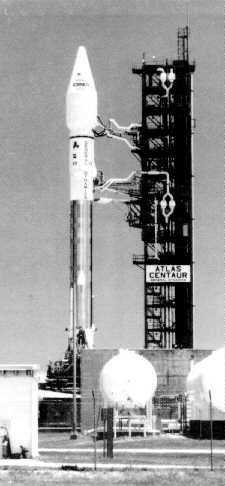
Atlas-Centaur
In May 1988, the Air Force awarded a contract to General Dynamics to develop and produce the Atlas II as a new medium launch vehicle. Its primary mission is to launch the Defense Satellite Communication System III satellites.30 General Dynamics stretched the Atlas stage nine feet to increase the amount of propellant (liquid oxygen and RP-1) the booster could carry. Engine improvements have increased launch thrust to almost 500,000 pounds. Additionally, the Centaur was stretched by three feet to accommodate more fuel (liquid oxygen and liquid hydrogen). The Atlas II can use either the 11- or 14-foot PLF. As in earlier versions, tank structural integrity is maintained at all times by either internal pressurization or, while on the ground, the application of a mechanical stretch.31
Two additional planned versions of the Atlas II are the Atlas IIA and the Atlas IIAS. Atlas IIA and IIAS will have upgraded RL-10 Centaur engines with extendable nozzles. The Atlas IIAS will have four Castor IVA solid rocket motors to augment thrust at lift-off.
[Image 11K]
Titan II
The Titan family of rockets spans the medium and heavy lift categories. The Titan is one of the most successful and the largest space launch vehicle in the US inventory. Today's Titan family can trace its legacy back to the Titan I ICBM developed in the mid-1950s by the Martin Company (now Martin Marietta Astronautics Group). Development of the Titan I ICBM began in 1955 as a follow-on to the Atlas. The Titan I was the nation's first two-stage liquid propellant rocket and was the first underground silo-based ICBM. The next generation, the Titan II, was the first to use storable hypergolic fuel (Aerozine-50 and nitrogen tetroxide) and an inertial guidance system. The Titan II was man-rated for NASA's Gemini program and had 12 successful launches between April 1964 and November 1966.32
The third generation of Titan rockets, developed in 1961, was from the outset a space launch system under the management of the Air Force. The program objective was to design a set of building blocks to cover a comprehensive spectrum of future missions without the inherent problems of a tailored launch vehicle. The common core is basically a Titan ICBM with structural modifications to support larger payloads. There were eight versions of the Titan III. Each version was a combination of the core vehicle either with a specific upper stage or no upper stage. Six versions had various sized strap-on solid rocket motors.
Currently, there are two versions of the Titan in the DOD inventory. The first is the Titan II. Fourteen Titan IIs have been converted for space launch missions from the ICBMs deactivated by the Air Force in 1987. Potential modifications of the refurbished Titan II include adding either Castor IVA or GEM solid rocket motors, stretching the first stage, and adding two Titan first stages as strap-ons for additional thrust.
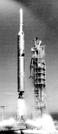
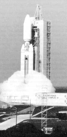
[Image 10K]
Titan IV
The largest space launch vehicle in the US inventory is the Titan IV (originally designated the Titan 34D-7). This program started as a short-term project to complement the space shuttle in assuring DOD access to space. However, after the Challenger accident in 1986 and the subsequent space shuttle fleet stand-down, it quickly became the DOD's main access to orbit for many heavy payloads. The first Titan IV launch occurred on 14 June 1989.
The Titan IV is made up of a two-stage core vehicle, two seven-segment solid rocket motors, and either an inertial upper stage--a Centaur--or no upper stage. The two seven-segment solid rocket motors attach alongside the 10-foot diameter core vehicle. The payload is encased within a 16.7-foot diameter PLF available in lengths of 56 to 86 feet. 3 A solid rocket motor upgrade (SRMU) program will allow the Titan IV to grow with the needs of its users. The SRMU program goals are to increase reliability, performance, and productibility. The Titan IV provides STS equivalent and greater payload lift capability enabling it to meet DOD unique requirements.
[Image 17K]
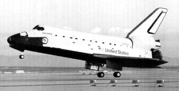
Space Transportation System
The Space Transportation System is a reusable system capable of deploying a wide variety of scientific and application satellites. Since it can carry payloads weighing up to 53,000 pounds, it can augment most of the expendable space launch vehicles currently in use. NASA can use it to retrieve satellites from Earth orbit, service or repair and then redeploy them, or bring them back to Earth for refurbishment and reuse. Scientists and technicians can use it to conduct experiments in Earth orbit. Thus, the STS is an effective means for use of current and future capabilities of space.34
The launch vehicle consists of an orbiter, two solid rocket boosters (SRB). and an expendable liquid propellant tank. The SRBs and three liquid propellant engines on the orbiter launch the system to an altitude of approximately 27 miles. The SRBs separate from the system and parachute to the ocean for recovery, refurbishment, and reuse. The orbiter continues the flight with the liquid propellant tank until main engine cutoff. Then the orbiter jettisons the external tank so that the tank reenters the atmosphere and falls into the ocean. The orbiter fires the engines of its orbital maneuvering system for a short period to gain power for insertion into Earth orbit. It can remain in orbit with a crew and payload for a period ranging from five to 20 days. It then returns to Earth and land like an airplane.
NASA launches the space shuttle from the Kennedy Space Center on Merritt Island, Florida. From the Kennedy Space Center, NASA can launch payloads into orbits of 28 to 57 degrees inclination. Landing operations are conducted at Edwards Air Force Base, California, and Kennedy Space Center, Florida, with backup at White Sands Missile Range, New Mexico.
The process of placing a payload into Earth orbit is not a simple or speedy task. Lt Col David E. Lupton in his book, On Space Warfare: A Space Power Doctrine, describes the launch process as similar to building an ocean liner from scratch, sailing it from Europe to the United States, and when within site of land using a rowboat to reach the shore while scuttling the ocean liner.35 The requirement to place a satellite in orbit takes a long road through the administrative (manifesting and documentation) and the physical (integration) phases. The following paragraphs describe this total process using the Delta II booster and Global Positioning System satellite as an example.
The process starts at the Launch Services Office (LSO) at Air Force Space Command. The LSO collects and documents space launch user requirements, coordinates expendable and manned launch system manifests, identifies launch conflicts and recommends options for resolution, and provides space launch support plans for all Air Force operated extraterrestrial launch vehicles and for DOD use of the space shuttle.
The LSO collects and consolidates user requirements to create three basic documents. The AFSPACECOM National Mission Model (ANMM) identifies needed upgrades to current launch systems and requirements for new or follow-on launch systems.37 The ANMM identifies launch requirements for up to 20 years in the future, is solely requirement driven, and is not encumbered by launch capability constraints. The second document is the DOD Spacelift Mission Model (DSMM) which comprises the first 13 years of the ANMM. The Space Launch Advisory Group uses the DSMM to advise the secretary of the Air Force on launch planning activities. Drafters of the president' s budget and the future years' defense plan use the DSMM (once the Space Launch Advisory Group approves it) and the ANMM.38
The first three years of the DSMM is known as the spacelift manifest. The manifest is an executable spacelift plan and is capacity constrained. It establishes the order or sequence of launches based on user requirements for each system, and it attempts to find the optimum mix of users and existing launch capabilities. The space launch wings use the manifest to generate their operations schedules.39
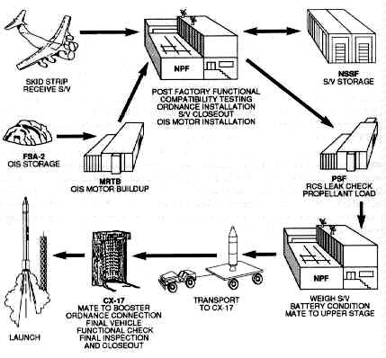
The paperwork trail for launching a satellite can be a long one. But, once authorities have approved the requirements and the launch is on the operations schedule, the launch base processing flow can begin (fig. 9). The processing flow for a Delta II booster and a GPS satellite nominally runs about 60 days. This schedule involves a five-day workweek at 1.5 shifts per day.40
Source: 6555th Aerospace Test Group Briefing,Cape Canaveral AFS, May 1991.
Figure 9. Launch Base Processing Flow
The delivery of the satellite via air transport to Cape Canaveral Air Force Station initiates the flow. The satellite either awaits processing in the Navstar Satellite Storage Facility or goes directly to the Navstar Processing Facility (NPF). In the NPF, the satellite undergoes post-factory functional testing, compatibility testing, ordnance installation, and installation of the apogee kick motor or orbit insertion system that will place the satellite in its final operational orbit. From the NPF, the GPS satellite proceeds to the payload servicing facility for the hazardous operations of reaction control system (RCS) leak checks and loading the hydrazine (the RCS propellant).
Preparation of the booster takes place concurrently. The McDonnell Douglas Space Systems Company plant in Pueblo, Colorado, delivers the two stages of the Delta II. The stages are off-loaded and prepared for Delta mission checkout (DMCO). DMCO tests the entire two-stage booster to include an integrated functional test (preflight off the launch complex), electrical and hydraulic tests, and a composite check putting both stages through the entire flight program.41
Once the initial ground testing is complete, the second stage proceeds to the High Pressure Test Facility to test tank and system integrity. The facility uses high pressure nitrogen and helium to verify the system. Additionally, crews install the stage II range safety destruct harness. The second stage then continues to the launch complex to await the completion of processing of stage I.42
At the completion of DMCO, stage I goes to the Horizontal Processing Facility for the installation of the range safety destruct harness. Next, stage I continues to the launch complex and is erected. This usually takes one day and is followed by the installation of the solid rocket motors. The nine graphite epoxy motors are in sets of three with each set requiring one day for installation. Launch complex personnel pressure check the GEMs and install the ordnance. The interstage or "beer can" (a spacer between stage I and stage II) is installed, followed the next day by stage II installation. The simulated flight test is the culmination of the booster erection.43
Now, the launch is within days. The satellite, which has been waiting in the NPF, is transported to the launch complex and erected on the booster. Next is the final flight program verification, ordnance hookup, and installation of the payload fairing. At launch minus two days, the hypergolic fuels (nitrogen tetroxide and Aerozine-50) are loaded aboard stage II. On launch minus one day, all final checks in addition to the range safety destruct tests are complete. The terminal countdown runs approximately eight hours. Four hours prior to launch, the fuels (RP- l and liquid oxygen) are loaded aboard stage I.44
The main engine and six of the GEMs ignite at T-O. Early after launch, a roll program turns the booster to the appropriate flight azimuth. Before launch plus 60 seconds, the six GEMs burnout, the three remaining light, and the craft jettisons the depleted motors. The remaining GEMs burnout and separate at launch plus 122 seconds. Main engine cutoff (MECO) occurs at launch plus 264 seconds.45
Stage I separation occurs eight seconds after MECO, followed five seconds later by stage II ignition (fig. 10). The payload fairing is jettisoned at launch plus 298 seconds at an altitude where the free molecular heating rate is within tolerance. Stage II burns until launch plus 687 seconds followed by a 10-minute coast period. Stage II/stage III (satellite and orbit insertion system) separation follows a short 20-second burn. At the appropriate equatorial crossing, stage III ignites placing the satellite in its proper orbit awaiting the beginning of system checkout.46
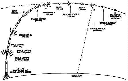
Source: 6555th Aerospace Test Group Briefing,Cape Canaveral AFS, May 1991.
Figure 10. Typical Delta II Mission Profile
1. AFM 1-1, Basic Aerospace Doctrine of the United States Air Force, vol. 1, March 1992, 7.
2. AFM 2-25, Space Operations, 29 March 1991, 18.
3. MSgt Warren Wright, "Quayle Announces New Launch Strategy," Space Trace, September 1991, 4.
4. TSgt Dennis Sanchez, "Eastern and Western Ranges" (Unpublished paper, AFSPACECOM/DOS, May 1992), 2.
5. Ibid.
6. Ibid., 3.
7. Ibid.
8. Ibid.
9. Ibid.
10. Defense Science Board, 1989 Summer Study on National Space Launch Strategy (Washington, D.C.: Office of the Under Secretary of Defense for Acquisition, March 1990), 13.
11. "Air Force Space Command Paper" (AFSPACECOM/DOSL, 16 September 1991), 13.
12. Ibid.
13. Ibid.
14. Ibid., 14.
15. Ibid., 10.
16. Ibid.
17. Ibid.
18. Ibid.
19. Ibid.
20. Ibid., 11.
21. Ibid. , 2.
22. Ibid., 3.
23. Ibid., 2.
24. Ibid., 3.
25. Ibid., 4.
26. Ibid.
27. Ibid.
28. Ibid., 6.
29. Ibid., 8.
30. Ibid.
31. Ibid.
32. Ibid., 15.
33. Ibid., 18.
34. Air Command and Staff College, Space Handbook (Maxwell AFB, Ala.: Air University Press, 1985), 13-1 through 13-14.
35. Lt Col David E. Lupton, On Space Warfare: A Space Power Doctrine (Maxwell Air Force Base, Ala.: Air University Press, June 1988), 23.
36. Sanchez, 3.
37. Ibid., 4.
38. Ibid.
39. Ibid., 5.
40. Maj Andrew Kraska, Director of Operations, 1st Space Launch Squadron, Cape Canaveral Air Force Station, telephone interview with the editor, May 1992.
41. Ibid.
42. Ibid.
43. Ibid.
44. Ibid
45. TSgt Dennis Sanchez, "Delta" (Unpublished paper, AFSPACECOM/DOS, May 1992), 4.
46. Ibid.